- Productos
- Soldadura en pasta
- Flux líquido y en pasta
- Soldadura en alambre
- Soldadura en barra
- Aleaciones de soldadura
- Materiales de soldadura adicionales
- Libre de Halógenos
- Materiales de soldadura para la industria LED
- Materiales de soldadura para la Industria Automotriz
- Materiales de soldadura para Militar y Aeroespacial
- Servicios
- Soporte
- Hojas de Datos
- Noticias
- Contacto
- Acerca
By Karl Seelig, Vice President Technology and Tim O’Neill, Technical Marketing Manager
A Tale of Fresh Eyes, Red Herrings and Dirty Tweezers…
We recently received a call from a contract assembler that was fighting solder balls after reflow. They were getting solder balls on one capacitor and tried to address it with profile changes. Sometimes the problem went away, but it always came back. They were also getting blowholes in the same solder joints from time to time.
First, we tried to identify the root cause for the balling problem remotely. The typical questions when confronted with this issue include:
-
On which components are the solder balls occurring?
-
Are the defects consistently in the same spot/component, or do their locations vary?
-
Was the solder paste fresh and permitted to warm to room temperature per the handling guidelines?
-
Were the boards misprinted and wiped or cleaned?
-
Have they tried baking the boards and components to dry them and determined any affect on the problem?
-
What is the reflow profile, and have they tried changing it and observing the results?
The answer to everything was yes. So Guru moved down the line to see if placement was affecting the solder paste deposit and promoting reflow problems:
-
Was the placement accurate?
-
Was placement pressure correct and appropriate?
-
Was the air kiss blowing paste around?
-
Were nozzles picking up solder paste and redepositing it?
-
Was there any interference from the board support fixture?
-
Was table movement causing component shift?
All these potential variables checked out, so it was time to move down the line again to the oven.

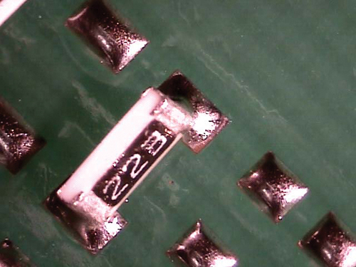
FIGURE 1. Component billboarding, where the part stands on its side.
We optimized a profile for the board and got QA’s approval to begin production, but upon starting we immediately ran into an issue. The component with the solder balling problem was also “billboarding” (FIGURE 1). The billboard defect, in which a chip component stands on its side (unlike a tombstone, which stands on one end), is typically not a reflow problem, but rather a placement issue caused by mispicking the part.
Before heading back to the P&P to check the feeder, tape and nozzles, we asked the inspector if this defect was also common. We were told that the billboard was not a defect, but part of the customer’s specification. Sure enough, the component was being correctly placed by the P&P, and then an operator would use tweezers to manually flip the component on its side per the spec. We don’t know why the customer specified the component be placed on its side. The underlying reason doesn’t really matter because the assembler must build to their customers’ specifications regardless. If the customer wants the component mounted on its side, the best we can do on the factory floor is accommodate their spec and try to optimize the resulting nonstandard process.
We provided the operator a clean pair of tweezers and emphasized the importance of a steady hand, explaining that stray solder paste on the component becomes solder balls that are considered defects and must be removed. We started up the line and built a five-board sample with the optimized profile, clean tweezers and a new understanding. QA approved them with flying colors, and the assembly line returned to production with the solderballing defect in check.
Dirty tweezers… go figure. Not printing, not placement, not profile, not outgassing – just a dirty hand tool. All the remote troubleshooting in the world would not have pinpointed this root cause. Had the reflow Guru ignored the billboard as an unrelated placement defect, we’d have missed it. This was one of those problems that just needed a fresh set of eyes and the tenacity to investigate every clue. Oh, and clean tweezers.
Download:


