ABSTRACT
As the electronics industry continually strives for innovation and efficiency in assembly and rework processes, the exploration of low temperature (LT) solder alloys has gained significant attention. This paper provides a comprehensive analysis of LT solder, particularly focusing on its application in rework processes and the broader implications for electronics manufacturing. We delve into various facets of LT solder, examining both the potential benefits and the challenges associated with its use.
The study revisits previous work on LT solder in rework, offering a detailed summary and suggesting a cautious approach due to the increased costs and complexities associated with bismuth-containing solder wire, alongside a lack of substantial differences in joint strength and reliability compared to traditional methods. Additionally, the paper addresses broader considerations of LT solder, including benefits and drawbacks, performance tradeoffs, and areas for further study.
This investigation into LT solder is further enriched by new data on the cleaning of bismuth oxide residues and the effects of tip temperature and contact time on IMC formation during rework. By providing a thorough overview of existing research and new findings, this paper aims to offer valuable insights to manufacturers, engineers, and researchers, contributing to informed decisions regarding the adoption and integration of LT solder in electronics rework and assembly.
INTRODUCTION
In an era where innovation and efficiency have become paramount, the electronics manufacturing industry constantly seeks avenues to improve processes, reduce costs, and enhance product reliability. Among the various solutions explored, low-temperature (LT) solder has emerged as a promising alternative to traditional soldering methods, especially with the proliferation of intricate, miniaturized electronics.
Historically, the use of LT solder has been motivated by its unique characteristics, such as a reduced melting point and the potential for energy and material savings.[1] However, as with any significant shift in methodology, the implementation of LT solder has brought forth its set of challenges. These challenges, from reliability to rework concerns to residue management, call for deeper exploration and understanding.
This paper delves into the intricacies of LT solder, specifically within the realm of electronics rework and assembly. Through rigorous examination and a combination of experimental data and industry insights, we aim to shed light on the true potential, benefits, and considerations of employing LT solder in contemporary electronics manufacturing.
BACKGROUND
Information about key features and issues associated with LT soldering is often disparate, with both ongoing and existing studies mired by differences in methodologies, entanglement with marketing efforts, and lack of meta-analytical conclusions solid enough to provide direct and actionable insights to manufacturers. This paper seeks to begin the process of bringing existing information together into a cohesive picture, identifying both benefits and challenges associated with LT soldering across different dimensions while clearly delineating remaining questions and areas of study as well as standardized conclusions from existing work.
Low Temperature Alloys
LT solders are characterized by their unique metal compositions, primarily involving tin (Sn) and bismuth (Bi). Historically, the presence of lead (Pb) in solders was common, but with the shift towards lead-free processes, bismuth has become a more viable component.[2] The prominence of tin and bismuth in these alloys marks a significant shift in solder technology. Bismuth, previously overlooked due to its incompatibility with Pb-based processes, is now integral to LT solders, particularly as most soldering processes have transitioned to being Pb-free. This transition has spurred the development of new generations of LT solders. While there is a growing variety of LT solder compositions emerging, this paper will primarily focus on eutectic tin-bismuth and tin-bismuth with a small addition of silver (Ag), as these compositions represent a significant portion of current LT solder applications.
Primary Benefits and Drawbacks of LT Solder
The primary benefits of LT solder lie in its lower melting temperatures compared to traditional solders. This characteristic leads to several advantages. The first is reduced energy usage. The lower melting point allows for energy savings during the soldering process, as less heat is required. In fact, some studies have shown potential energy savings of up to 20-40% using low temperature reflow profiles vs those for traditional SAC305.[3]
Another advantage is decreased component warpage. Lower temperatures reduce the risk of warping sensitive components during soldering, thereby enhancing product integrity.
However, these benefits are counterbalanced by certain drawbacks. Notably, bismuth, while advantageous for lowering the melting point, introduces brittleness to the solder joints. This can affect the reliability and durability of the soldered connections, especially in environments where mechanical stress is a concern.
Another drawback is related to temperature sensitivities. While lower temperatures are beneficial for energy savings and reducing warpage, they also necessitate careful control and calibration during the soldering process to ensure the integrity of the joint.
There are also questions related to the creation of hybrid joints (often SAC+LT) in various scenarios and what the characteristics and failure modes of such joints are.[4] This is something we previously investigated in the case or rework using low temperature solder. Changes in process is another area of exploration, such as adjusting ramp rates and using reflow ovens with cooling zones. [5][6]
Low Temperature Solder In Rework
One question many manufacturers have when implementing low temperature solder processes is whether they can or should also use low temperature solder in any rework done on components that have been soldered with LT solder. This question is twofold – first, whether LT solder in the process requires LT solder in rework to maintain joint integrity, and second, whether using LT solder in rework yields additional benefits and cost savings, similar in the way LT solder used in reflow and wave soldering does.
The discussion aims to provide a comprehensive understanding of LT solder’s role in rework, highlighting key considerations for manufacturers contemplating its adoption in their repair and maintenance protocols.
Summary of Previous Study
The original study explored the viability of LT alloys in rework scenarios.[7] It was observed that low-melting temperature solid wire and external flux, as well as flux-cored SAC305 wire solder, could be successfully employed for reworking LT alloys. The LT solder exhibited distinct processing characteristics compared to SAC solder, but these did not impede the formation of quality solder joints.
Crucially, solder joints created with LT solder met the IPC Class 1, 2, 3 criteria, suggesting that LT solder is a viable option for a range of product classes. However, shear test results were variable, reflecting the inherent challenges in rework processes. SAC solder joints demonstrated greater ductility compared to their bismuth-bearing counterparts, which aligns with the known material properties of these alloys. When SAC305 flux-cored wire solder was used, the process resembled traditional SAC/SAC rework methods, with an emphasis on utilizing finer wire diameters for smaller components.
The study highlighted the importance of operator skill, underscoring the need for adequate training when implementing LT rework. This is particularly relevant given the variable nature of rework results, even under the guidance of a highly experienced operator.
Unresolved Questions from the Initial Study
Several questions remained unresolved, warranting further investigation. One of the key unresolved issues is the cleanability of bismuth oxide residue post-reflow and rework. This aspect is crucial for ensuring long-term reliability and performance of the soldered joints.
The original study also indicated that variables in hand soldering techniques, particularly tip temperature and contact time, significantly impact the formation of intermetallic compounds (IMCs). Understanding these variables is essential for optimizing rework processes and ensuring the integrity of solder joints.
These unresolved questions were investigated as described in the next two sections.
Cleanability of Bismuth Oxide Residue
One of the primary concerns surrounding the use of LT solder is the potential for bismuth oxide residue to remain after the reflow and rework processes. The presence of this residue may impact the quality and reliability of the solder joint, though it is primarily considered cosmetic. A study was performed in partnership with MicroCare to determine whether this residue was cleanable and which cleaning chemistry performed the best.
Purpose of the Experiment
The study aimed to assess the effectiveness of various cleaning chemistries in removing residues from solder joints created using low-temperature (LT) solder. This study was particularly focused on evaluating different cleaning agents’ ability to clean bismuth oxide residues resulting from LT soldering processes.
Materials Used
In this study, various solder materials were employed. The selection included AIM M8 SAC305 paste, NC273LT Sn42/Bi57/Ag1 paste, SAC305 flux core wire, and solid Sn42/Bi57/Ag1 in combination with NC280 (for PTH components) or NC217 (for SMT components) flux.
To evaluate the cleaning process, three distinct cleaning chemistries were considered. Two of these were fluorinated cleaners, denoted as Cleaners X and Y, while the third was a non-fluorinated cleaner named Cleaner Z.
Experimental Setup and Procedure
For the assembly and testing phase, test coupons (PCB016) were created for each cleaner under examination. The assembly process involved multiple steps. Coupons A and B were both reflowed with LT solder and reworked using LT wire and external flux. Coupon C underwent reflow with LT solder and rework with flux cored SAC305 wire. Coupon D experienced both reflow and rework with SAC305. Lastly, Coupon E was reflowed with LT solder and did not undergo any rework. The initial step in this phase included capturing “Before” pictures of all components.
The subsequent benchtop cleaning procedure involved the application of cleaning solvent using a dispensing tool. The process comprised a wet scrub and dry cycle, consisting of a 20-second wet scrub, a 20-second scrub, and a 30-60 second drying period. The cleanliness of the coupons was then meticulously analyzed under a microscope, followed by capturing “After” pictures.
Results
After thorough experimentation, Cleaner X emerged as the most effective cleaner for the samples under consideration. The cleaning effectiveness was further assessed by examining specific test coupons. Test Coupons B, C, and E exhibited the most satisfactory cleaning results with Cleaner X, signifying successful residue removal with LT+LT, LT+SAC, and LT without rework, respectively (refer to Figure 1). However, Test Coupon A (LT+LT) showed slight residue in certain areas, contrasting with its twin, Test Coupon B. Test Coupon D (SAC+SAC) displayed several areas of noticeable residue post-cleaning, as illustrated in Figures 2 and 3.
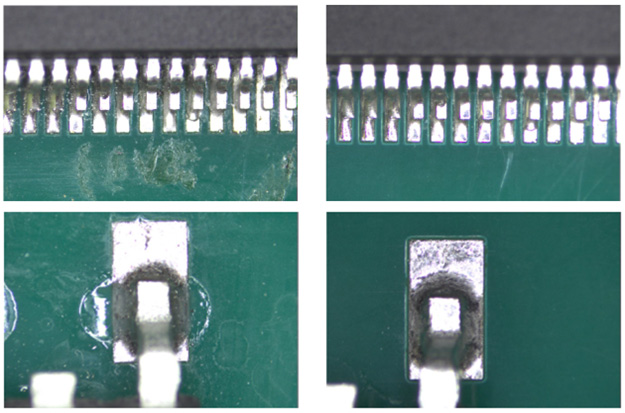
Figure 1. Components on Test Coupon C before (left) and after (right) cleaning with Cleaner X

Figure 2. Test Coupon A before (left) and after (right) cleaning with Cleaner X

Figure 3. Test Coupon D before (left) and after (right) cleaning with Cleaner X
Conclusion
The study concluded that while the cleaning process using Cleaner X was effective for most test coupons, there was notable variability in residue removal across different samples. The study underscores the importance of selecting the appropriate cleaning chemistry and rigorously following the cleaning procedure to ensure effective residue removal.
IMC Growth Considerations and Variables in Hand Soldering Techniques
Intermetallic compound (IMC) growth is a crucial factor in assessing solder joint reliability. The initial study had shown comparable results between various soldering combinations in terms of shear testing and IMC thickness. However, the rate of IMC growth and the importance of dwell time in this formation are still subjects of intense scrutiny. Unraveling the dynamics of IMC growth in the context of LT solder can provide more clarity on the solder’s long-term viability.
Effects of Hand Soldering Variation on IMC and Other Features
This study was initiated to address the second follow-up question from the initial Low Temperature Rework paper.[7] Metcal, a company specializing in manufacturing hand soldering equipment, the impact of tip temperature and contact time on the formation of intermetallic compounds (IMC) and other characteristics when using Low Temperature Solder (LTS) was investigated.
Materials Used
The study used the alloy Sn42/Bi57/Ag1 for both reflow and rework, with AIM flux NC280 being used alongside the wire. The components soldered were five plated-through-hole (PTH) components, comprising three resistors and two capacitors, on a single PCB model. Hand soldering was performed with a CVC-6CH0025S Soldering Iron with a 2.5 mm chisel tip.
Experimental Setup and Procedure
The soldering conditions were varied in this experiment, involving two different tip temperatures, namely 285°C and 343°C, with corresponding adjustments in contact times. Specifically, for 285°C, the contact times were set at 3s, 4s (baseline), 5s, and 6s. Meanwhile, at 343°C, the contact times were 2s (baseline), 3s, 4s, and 5s.
The evaluation parameters focused on a comprehensive analysis of various aspects, including solder joints, residue characteristics, wetting properties, corrosion, form of solder joint, barrel fill confirmation, IMC thickness, and the presence of voids.
Results
In the examination of solder joints, it was observed that some joints exhibited a contact angle exceeding 90° at 285°C, particularly notable at a 3-second contact time. Conversely, at 343°C, certain joints displayed excess solder on the top side, as depicted in Figure 4.
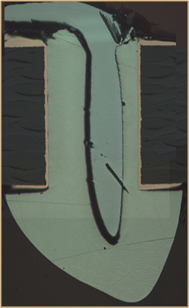
Figure 4. Contact angle of capacitor pin after rework at 285°C, 3 second contact time
Regarding residue, the color darkened in correlation with the contact time for both tip temperatures, as illustrated in Figure 5.
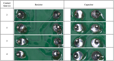
Figure 5. Underside residue of reworked components at 343°C
The wetting properties of the solder were noteworthy, presenting a shiny, smooth appearance and providing good pad area coverage across the majority of joints.
No instances of corrosion were detected in the analyzed PCBs.
The form of solder joints was influenced by the temperature conditions. Components subjected to 343°C formed better solder joints across different contact times compared to those at 285°C. All barrels, except for the resistor with 3 and 4 seconds of contact time at 285°C, were filled to 100%.
The investigation into IMC thickness revealed that at 343°C, the PCB/Solder IMC was higher compared to the Pin/Solder IMC. The thickness of IMC was greater for components with 3 and 4 seconds of contact time than those with 2 and 5 seconds. At 285°C, the Pin/Solder IMC was higher than the PCB/Solder IMC, especially for resistors with contact times of 6 and 5 seconds. Capacitors at 285°C did not show measurable Pin/Solder IMC, suggesting it was less than 1µm. Refer to Figure 6, Table 1, and Table 2 for detailed information.
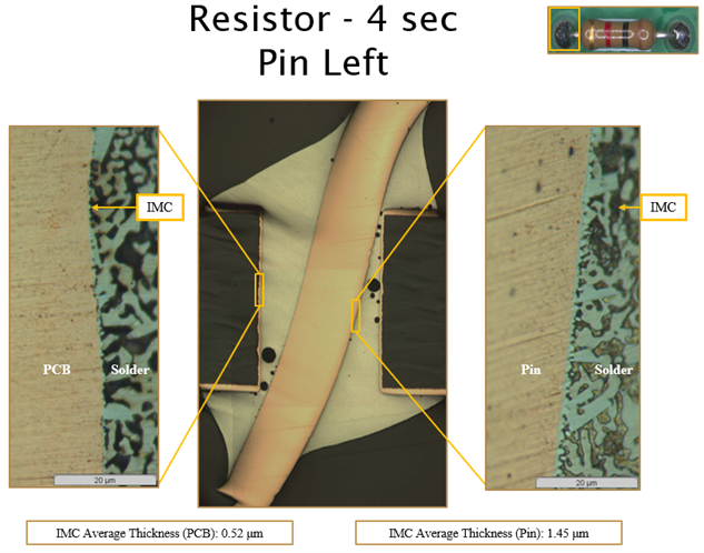
Figure 6. IMC thicknesses after rework of resistor pin at 343°C, 4 second contact time
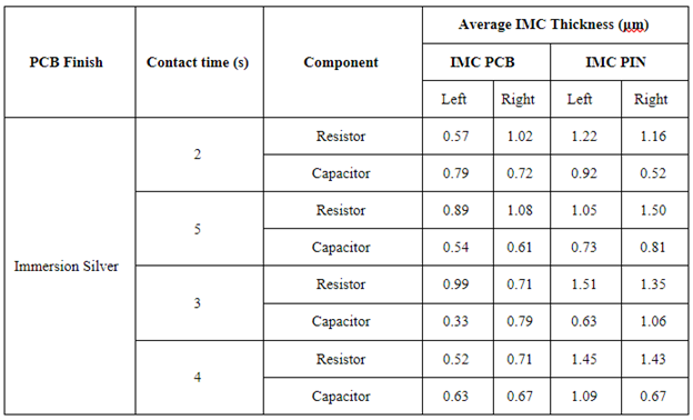
Table 1. Average IMC Thickness 343°C
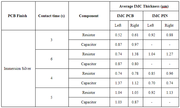
Table 2. Average IMC Thickness 285°C
Finally, the presence of voids was a common observation, with more than 80% of the pins showing voids for both temperatures and across different contact times.
Conclusions
The findings indicated that differing temperatures and varying contact times influence the quality of the solder joint and IMC formation. For the question as to whether using LT solder in rework might extend tip life or save energy, the answer appears to be no. Overall, the higher temperature, 343°C, yielded the best results, with 3-4 seconds being the ideal contact time.
Further Considerations for IMC Growth
Different rework approaches, such as LT+LT, LT+SAC, and SAC+SAC, may influence IMC formation uniquely. As manufacturers consider adopting LT solder for rework, it is imperative to understand these subtle differences and their potential implications. Many recent studies have looked at IMC growth as well as bismuth migration in BGAs, comparing the effects across LT+LT, LT+SAC, and SAC+SAC.[8] However, results from one study to another do not show a definite trend. There is also evidence that the temperature ramp, cooling rates, and dwell times may significantly impact joint integrity as well when it comes to low temperature solders whether they are or are not part of a hybrid joint, as mentioned previously. This would seem to indicate the potential for further variation in results from hand soldering, depending on equipment settings as well as operator experience.
Outlining the Case for LT Solder in Rework
In examining the potential benefits of using low-temperature (LT) solder in rework processes, several key factors must be considered. Our studies and research have provided insights into each of these aspects, shaping our understanding of the practicality and efficacy of LT solder in rework scenarios.
Solder Material Cost Savings
Contrary to expectations of cost-effectiveness, LT solder wire is significantly more expensive than SAC305. This is because a key component of LT solder, bismuth, is not very ductile, making the manufacture of LT solder wire inherently more challenging. This higher cost undermines one of the potential advantages of using LT solder in rework processes, making it a less appealing option from a financial standpoint.
Ease of Use
Ease of use is another area where LT solder does not necessarily offer advantages. The requirement for non-cored wire and external flux complicates the rework process. Additionally, it demands a higher level of expertise and precision from the operator. These factors contribute to a more challenging and intricate rework process.
Energy Savings
While LT solder melts at lower temperatures, which suggests potential energy savings, our findings indicate that joint integrity and IMC formation is improved when using a hotter tip temperature and moderate contact time. This would indicate that there are no energy savings to be had in rework without compromising the integrity of the work.
Tip Life
Although there is a theoretical possibility of extended tip life due to lower operating temperatures, our research again suggests this would not be born out due to the improved results when soldering at a higher temperature.
Integrity of the Joint
Our initial study compared the performance of SAC+SAC, LT+SAC, and LT+LT configurations in terms of shear testing and IMC thickness. The results indicated that all these combinations were comparable in performance. However, questions remain about the IMC growth rate and dwell time, which require further investigation to fully understand the implications on joint integrity.
Component/Substrate Temperature Requirements
An important consideration in the use of LT solder is its impact on component and substrate. If the adoption of LT solder in reflow processes leads to the use of cheaper substrates and components, these may have specific temperature sensitivities in rework that must be carefully managed. This aspect of LT solder usage necessitates a nuanced understanding of the materials involved and their respective temperature tolerances.
Residue Cleanability
Bismuth containing solders can leave behind bismuth oxide residue, both after reflow and after rework. In fact, much of this residue was observed on the reworked components in the solder iron variable study. It was determined, however, that a cleaning solution and process exist that virtually eliminates this residue.
Conclusion
Based on the cumulative insights from our research and studies, the case for using LT solder in rework processes is not strongly supported. While there are theoretical benefits, the practical realities and findings from our investigations suggest that the advantages are either minimal or negated by other challenges. Manufacturers must weigh these factors carefully when considering the adoption of LT solder for rework purposes.
Low Temperature Solder Primary Use Cases
Finally, we would like to re-evaluate the broader scope of low-temperature (LT) solder applications, considering both its inherent limitations and areas where it shows promise.
Recall that LT solders exhibit lower reliability in scenarios involving mechanical stress, such as drop shock, where brittleness can be a significant hindrance. However, they may be well-suited for consumable electronics where high durability is less critical, and keeping manufacturing costs low is essential for maintaining profitability.
Controlled Application Environments
In cases where the device is not expected to undergo significant mechanical stress, such as in stationary or controlled environments, the brittleness of tin-bismuth solder may not be a major concern.
Combination with Other Alloys
Sometimes, tin-bismuth solder can be combined with other alloys to mitigate its brittleness. For example, adding silver (Ag) can improve its mechanical strength, making it more suitable for applications that require some level of shock resistance.
Redundant or Non-Critical Components
In some designs, particularly in automotive and aerospace, tin-bismuth solder might be used for components that are either redundant or not critical to the primary function of the system, thereby reducing the risk associated with solder joint failure.
Flexible Electronics
In flexible electronics, the focus is often on flexibility rather than mechanical shock resistance. Here, the low temperature of tin-bismuth solder is beneficial for temperature sensitive materials used in these devices. The devices themselves might be designed to experience minimal impact or shock.
Use in Protected Components
In both automotive and aerospace applications, components soldered with tin-bismuth might be housed in mechanically protected areas where the likelihood of experiencing drop shocks is minimized.
Selective Application
Tin-bismuth solder might be used selectively in conjunction with other types of solder in a single assembly, employed only in specific areas where its low melting point is beneficial, and its brittleness is not a significant drawback.
Advanced Packaging Techniques
Some modern electronic packaging techniques can mitigate the effects of solder brittleness, such as using underfill materials or employing specific PCB designs that reduce stress on solder joints.
Non-Moving Parts
In automotive and aerospace, it might be used for non-moving parts or in applications where the solder joints are not subjected to frequent or severe mechanical stresses.
Spotlight on Consumable Electronics
The consumable electronics segment is particularly intriguing when considering the adoption of LT solder. These are products often designed with a short lifecycle in mind, from mobile accessories to budget earphones. Note that while disposable devices using LT solder might negate positive environmental benefits of LT solder use by contributing to excess waste, in specific markets where electronic devices are required to be disposable (like certain medical or security applications), LT solder can help maintain cost-effectiveness.
Future Directions and Recommendations
The exploration of low-temperature (LT) solder, its application in rework, and its broader implications for the electronics industry has undoubtedly yielded a wealth of knowledge. However, as with any scientific endeavor, the journey has uncovered as many questions as it has answered. Drawing on the insights gathered thus far, several future directions and recommendations emerge.
Alloy Development and Standardization
In an iNEMI study, respondents indicated a desire for there to be a standard alloy in LT before they wanted to invest in making the switch.[9] As discussed up top, while eutectic tin bismuth is the “basic” model which more sophisticated LT alloys are often compared to or modified from to resolve existing issues, there is still much experimentation going on with addition of dopants and other elements.
Improving the reliability of low-temperature tin-bismuth (Sn-Bi) solders often involves the addition of other elements to the alloy. These additions are intended to enhance certain properties like mechanical strength, thermal cycling performance, and brittleness reduction. Some of the most effective elements for this purpose include:
- Silver (Ag): Adding silver to Sn-Bi alloys is one of the most common methods to improve their mechanical strength and thermal fatigue resistance. Silver can enhance the overall robustness of the solder joint, making it less prone to failures under mechanical stress or thermal cycling.
- Copper (Cu): Copper is another element often added to Sn-Bi solders. It can improve the wetting characteristics of the solder and enhance its mechanical properties. Copper also helps in reducing the rate of IMC (Intermetallic Compound) growth, which can be beneficial for long-term reliability.
- Nickel (Ni): Nickel is used to enhance the mechanical properties of the solder and to stabilize the intermetallic layer, reducing the growth of brittle phases. This can be particularly beneficial in applications where the solder joints are subjected to mechanical stress.
- Antimony (Sb): Antimony can be added to Sn-Bi solders to improve their thermal and mechanical properties. It helps in refining the solder’s microstructure, leading to better performance under thermal cycling and stress.
- Indium (In): Indium can increase the ductility of the solder, making it less brittle. This can be particularly useful in applications where flexibility and resistance to thermal fatigue are important.
Each of these elements contributes in different ways to the solder’s overall performance. The choice of which element(s) to add depends on the specific requirements of the application, such as the operating environment, the types of stresses the solder joints will encounter, and the desired balance between cost and performance. The proportions of these additives need to be carefully controlled, as excessive amounts can lead to other issues such as increased brittleness or reduced wetting ability.
Determining the Business Case for Low Temperature Solder Today and in the Future
Determining the business case for low-temperature (LT) solder involves assessing both immediate and long-term factors in electronics manufacturing. Key considerations include the cost comparison between LT and traditional solders, factoring in potential long-term savings from reduced energy usage and the possibility of using cheaper components. The compatibility of LT solder with existing manufacturing lines, alongside the requirement for equipment modifications, forms a critical part of this evaluation.
Product-specific requirements, particularly for temperature-sensitive components, and the reliability and performance of LT solder under various conditions, are essential to consider. Additionally, environmental benefits and regulatory compliance, aligned with global sustainability trends, play a significant role in this assessment.
Future prospects, such as the trend towards miniaturization in electronic devices and market shifts towards more environmentally friendly manufacturing processes, are also important. The business case for LT solder, therefore, hinges on a balance between immediate operational needs, long-term benefits, and adapting to evolving industry trends and consumer demands.
The Importance of Industry Collaboration
The path forward calls for a concerted effort in collaborative research, combining expertise from academia, manufacturing, and soldering technology to explore areas such as energy consumption, material interactions, and more. The establishment of open platforms for knowledge sharing, coupled with strengthened ties between industry and academia, will be crucial in addressing unresolved issues and fostering innovation. This collaborative approach promises to unlock the full potential of LT solder in electronics manufacturing, turning challenges into steppingstones for advancement and efficiency in this evolving field.
CONCLUSION
Our comprehensive examination of low-temperature (LT) solder in electronics assembly and rework has highlighted its complex role in modern manufacturing. The comparative analysis of various rework strategies revealed nuanced differences in terms of joint quality, IMC growth, and process time, shedding light on the best practices tailored for specific manufacturing goals. In summary, better reworked joints were formed using higher iron tip temperatures and moderate contact times. In addition, we were able to confirm that bismuth oxide residue resulting from either rework or reflow of low temperature bismuth containing solders was cleanable should this residue pose an issue.
Ultimately, we concluded that, while LT solder comes with many benefits in reflow soldering, there is not much of a case for the use of LT solder in rework due to the complexity, cost, and relative lack of any benefits over reworking with SAC. Moreover, until further discoveries produce more reliable LT alloys, we see drawbacks associated with brittleness and drop shock failures that must be balanced against the energy and cost savings of LT soldering pointing to consumable electronics being perhaps the best current use case.
Looking ahead, the development and wider adoption of LT solder will depend on addressing challenges through collaborative innovation, ongoing research, and adaptation to new industry requirements. The journey through LT solder’s intricacies suggests a path of continuous learning and adaptation, where industry collaboration can leverage its potential to meet the advancing demands of electronics manufacturing.
REFERENCES
[1] Tang, K. K., Aspandiar, R. F., Mokler, S., Chen, O., & Jiang, A. (2015). SMT Soldering with Low Temperature Solder Paste. Intel Corporation.
[2] Mei, Zequn & Hua, Fay & Glazer, J. & Chung, C. Key. (1997). Low temperature soldering. Circuit World. 10. 463 – 476. 10.1109/IEMT.1997.626966.
[3] Intel. (2017). Introduction to Low Temperature Soldering (LTS). Intel Corporation. Copyright 2017.
[4] Coyle, R., Anselm, M., Hadian, F., Kempaiah, S., Raj, A., Popowich, R., Clark, L., Fullerton, J., & Johnson, C. (2021, November 1). The Effect of Peak Reflow Temperature on Thermal Cycling Performance and Failure Mode of Hybrid Low Temperature Solder Joints. SMTA International 2021, November 1, 2021
[5] Dušek, K. & Bušek, David & Veselý, Petr & Pražanová, Anna & Plaček, Martin & Re, Julia. (2022). Understanding the Effect of Reflow Profile on the Metallurgical Properties of Tin–Bismuth Solders. Metals. 12. 121. 10.3390/met12010121.
[6] Sloan, M., Flanagan, K., Sandy-Smith, B., Allen, M. B. (2018). Reflow Profiling for Next-Generation Solder Alloys. Indium Corporation. Clinton, NY, USA.
[7] O’Neill, T., Fijalkowski, J., Tafoya, C., Xu, Y., Hrcek, S., Lambert, L., Willis, B., Hamasha, S. (Year). Addressing Low-Temperature Rework Concerns. AIM Solder. Montreal, Quebec, Canada.
[8] Fu, Haley & Aspandiar, Raiyomand & Chen, Jimmy & Cheng, Shunfeng & Chen, Qin & Coyle, Richard & Feng, Sophia & Hardin, Bill & Krmpotich, Mark & Mokler, Scott & Radhakrishnan, Jagadeesh & Ribas, Morgana & Sandy-Smith, Brook & Tang, Kok & Wu, Greg & Zhang, Anny & Zhen, Wilson. (2018). iNEMI project on process development of BISN-based low temperature solder pastes — Part II: Characterization of mixed alloy BGA solder joints. 1-17. 10.23919/PanPacific.2018.8318989.
[9] iNEMI. (2019). iNEMI Survey Summary Report: Low Temperature Solder (LTS) Readiness for Volume Board Assembly. Published in May 2019.
AUTHORED BY
Timothy O’Neill, Gayle Towell
AIM Solder
Cranston, Rhode Island, USA
Elizabeth Norwood
MicroCare
New Britain, Connecticut, USA
Hoa Nguyen
Metcal
Cypress, California, USA
*PRESENTED AT IPC APEX 2024
ACKNOWLEDGEMENTS
The authors would like to thank Yanci Gomez, AIM Solder R&D Technical, and Itzayana Lopez, AIM Solder R&D Chemist for their assistance in cross sectional analysis.


