Introduction. As the proliferation of modern day electronics continues to drive miniaturization and functionality, electronic designers/assemblers face the issue of environmental exposure and uncommon applications never previously contemplated.
This reality, coupled with the goal of reducing the environmental and health implications of the production and disposal of these devices, has forced manufacturers to reconsider the materials used in production.
Furthermore, the need to increase package density and reduce costs has led to the rapid deployment of leadless packages such as QFN, POP, LGA, and Micro-BGA. In many cases, the manufacturers of these devices will recommend the use of no clean fluxes due to concerns over the ability to consistently remove flux residues from under and around these devices.
These concerns, along with the need to implement a tin whisker mitigation strategy and/or increase environmental tolerance, have led to the conundrum of applying conformal coating over no clean residues.
The AIM Research & Development team has united with OEM electronics and conformal coating manufacturers in an attempt to characterize the different coating technologies currently available. In this study, various coating materials were tested with different chemistries of no clean fluxes. Results demonstrate possible combinations meeting the mission profile of the assembly with consideration for the assemblers’ capabilities and cost objectives.
Conformal coating of PCBs has garnered serious attention in all phases of PCB design and manufacturing. Manufacturers and Engineers industry-wide are exploring the capabilities, costs, and limitations of this technique. The driving factor being the deployment of electronics into more diverse and harsh environments as the demand for functionality and interoperability grows. These systems are being introduced to conditions that would have been considered unsuitable for electronics a short time ago, including condensing environments and dust environments. Some of the known benefits of coating include;
- Reducing entrapped surface contamination to contact power or ground areas
- Tin whisker mitigation
Having engaged multiple conformal coating manufacturers, there is a common recommendation for the application of conformal coating; that is that the substrate be cleaned prior to application, regardless of the type of coating to be applied. These same manufacturers will also admit that many of their customers are coating over no clean flux residues for a variety of reasons. The most common being;
- Cost of cleaning
- Throughput requirements
- Incomplete removal of ionic contamination under and around low-standoff devices
- Tin whisker mitigation
Analyzing final working environment is crucial to a successful outcome and should be the first consideration in determining the appropriate assembly process. One should determine if applying coating will a) achieve the desired outcome b) be practical given the nature of the assembly and the assemblers capabilities. Assuming coating is appropriate, the materials to be used need to be vetted.
In this study, we will address the findings of an in-depth analysis of various types of conformal coatings and how they perform in combination with a variety of no clean flux residues.
The following industry test standards were applied:
- IPC J-Std-004 SIR Testing
- IPC CC-830 - Qualification and Performance of Electrical Insulating Compound for Printed Wiring Assemblies
- ASTM – D3359 - Standard Test Methods for Measuring Adhesion by Tape Test
The three standards applied to this study will determine the SIR values and adhesion properties of each material in combination. These figures were compared with supplier provided data on the individual materials to determine if characteristics were measurably enhanced or degraded when combined. The classes of conformal coating materials tested are outlined below.
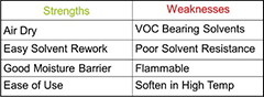
Acrylics Thermoplastics dissolved in solvents – no cross-linking
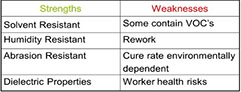
Urethanes Cure through cross-linking
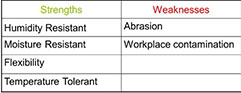
Silicones Cure through moisture cross-linking
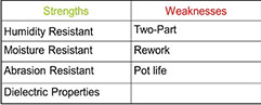
Epoxies Usually two-part systems
Acrylated Urethane UV Curable Urethane
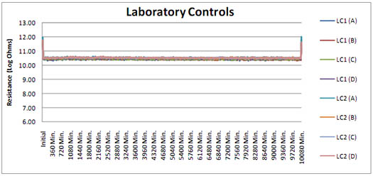
All of the samples tested passed IPC SIR testing without issue. An example of the data generated found below:
PASS-FAIL CRITERIA
IPC J-STD-004B §3.4.1.4.1
All measurements on all test patterns shall be exceed the 100 MΩ
No evidence electrochemical migration that reduces conductor spacing by more than 20%.
No corrosion of the conductors.
TEST RESULTS
1. Test data, chart attached, pass
2. Presence of dendrites: No
3. Maximum percent reduction of spacing: 0%.
4. Presence of discoloration between conductors: No
5. Presence of water spots: No
6. Presence of subsurface metal migration: No
Original test data available upon request.
Result Charts (1-3)


Adhesion testing/thermal shock testing was originally conducted on Practical Component SABER Test Assemblies; however after multiple tests it was determined that the required data could be collected using standard B-24 test coupons. In addition to a considerable cost savings, it eliminated variables that could have clouded the results including the presence of ionics, mold release agents and coating thickness variability.
The findings of the adhesion testing yielded some favorable and some unexpected results. The balance of this work focuses on solder paste. We did not test wire solder residues and all liquid fluxes where the conformal coating wet and adhered to the substrate at the time of coating/curing passed all subsequent tests.
Initial testing of thermal shock at -60°C - +125°C showed gross delamination. Initially, it was thought the failure was due to movement of the flux residue having softened at 125°C. Further examination revealed that there was a cohesive failure of the flux residue, wherein the flux remained firmly adhered to the PCB substrate and to the coating, but failed internally (photo 3). This phenomenon was present on all coatings in varying degrees (other than silicone). In general, UV materials performed the worst, with solvent-based acrylics better and silicones the best, with no delamination. A failure was considered any evidence of delamination. It was not determined if delaminated coating that remained contiguous was still effective in protecting the underlying substrate.
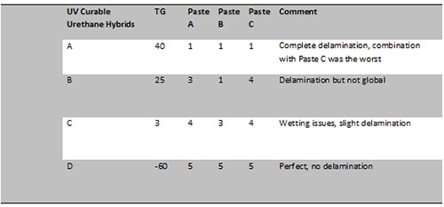
Ultimately, we found the modulus of the coating is directly correlated to cold temperature failure. The CTE mismatch of the residue and a high modulus coating were enough to fracture the cold hardened flux residue. Flux medium used in solder paste is typically a resin-based material and after reflow, the residue is hard. The colder the environment is, the harder the residue. To test this theory, we varied the residue and the coatings using harder and softer materials. UV curable silicone having the lowest modulus of the materials tested and UV cure urethane the highest. We also tested a paste that is not resin based with residue that is waxy, rather than hard. As depicted below, reducing the modulus of either the coating or the residue eliminated the delamination failure.
We also noted that solvent-based acrylic coatings outperformed UV cured urethane materials although it was product specific. It is believed that the solvent would facilitate a more intimate bond between the residue and the coating lessening the adverse effect of the CTE.
We went a step further to determine what the lowest temperature a resin based no clean paste and acrylic or acrylate/urethane coating can withstand before suffering delamination. The results of these tests were scattered, but none of the material sets were capable of withstanding more than -35°C for more than 10 cycles.
With this information, it would seem the simple solution to this problem would be to incorporate a softer residue solder paste to remedy the delamination issue. Unfortunately, there is a significant impact to the SIR characteristics as detailed below in Figure 1.
Figure 1. Moisture Absorption After Conformal Coat

Figure 2. Results: 1 to 5 (worst to best)
The results indicated that the silicon did not delaminate. Delamination is easy to see in the test as shown below. The following profile was used.
Figure 3. Profile

Figure 4. Pre Shock

Figure 5. Paste 55 Post T Shock Delamination

However if the solder paste is a low/no residue nitrogen reflow solder paste delamination does not occur.
Figure 6. Paste 16 (low/no residue) Pre T Shock

Figure 7. Paste 16 Post T Shock/No defects

The following are a series of photographs that identify the hard flux issue with delamination of a harder urethane coating.
Photo 1. Delaminated after thermal shock testing

Photo 2. Delamination lifting off board

Photo 3. The crystal flux residue left on the board

Photo 4. Crystal flux residue stuck to the coating

Photo 5. Close up of the above

Photo 6. Close up of the above

Conformal coatings are not hermetic with all the materials tested having varying degrees of moisture vapor transmission. In this case, whereas moisture enters the coating, the softer residue solder paste absorbs the moisture and creates a “pressure cooker” of corrosion and electrical failures (shown in figure 9).
Pictured below in figure 8 are SIR test results showing the beginnings of dendrites. These were run in 85°C/85Rh. SIR testing was also run at 40°C and 90 Rh. This test showed less failures compared to the 85°C/ 85Rh.
Figure 8. IPC 2.6.3.7 SIR Test (paste material coated with conformal coating).
The below picture is of a comb pattern that was run at 85°C/85Rh. The dendrites are starting to grow.
Figure 9. Comb Pattern w/ Dendrites

Adhesion to board and flux residues can also be determined by using a crosshatch cut and applying tape to check adhesion as shown in figure (s) 10 & 11.
Figure 10. Black Light/Good Adhesion

Figure 11. White Light/Good Adhesion

Conclusion. This writing is a consolidation of hundreds of tests and material combinations. The matrix of residues and available coatings would be too large to contemplate. The data has been edited to present key findings of collected information and provide practical guidance for engineers considering deploying this technique for their assemblies.
Based on our findings, we have concluded that conformal coatings can safely be used over no clean flux chemistry for many types of assemblies. It is imperative that compatibility testing be performed to ensure the coating provides the intended protection and meets the mission profile of the assembly.
The incorporation of low standoff devices and the ability to completely remove water soluble organic residues is driving more assemblers to consider a no clean process. The risk assessment of water soluble versus no clean in these applications consistently favors no clean. The cost savings in decommissioning the wash process and equipment is another major reason for migrating to no clean chemistries.
Finally, as conformal coating continues to be the only accepted practice for tin whisker mitigation, along with the looming expiration of the RoHS exemption, we predict no clean chemistries and the subsequent coating of the resulting residues will become increasingly prevalent over time.


